-
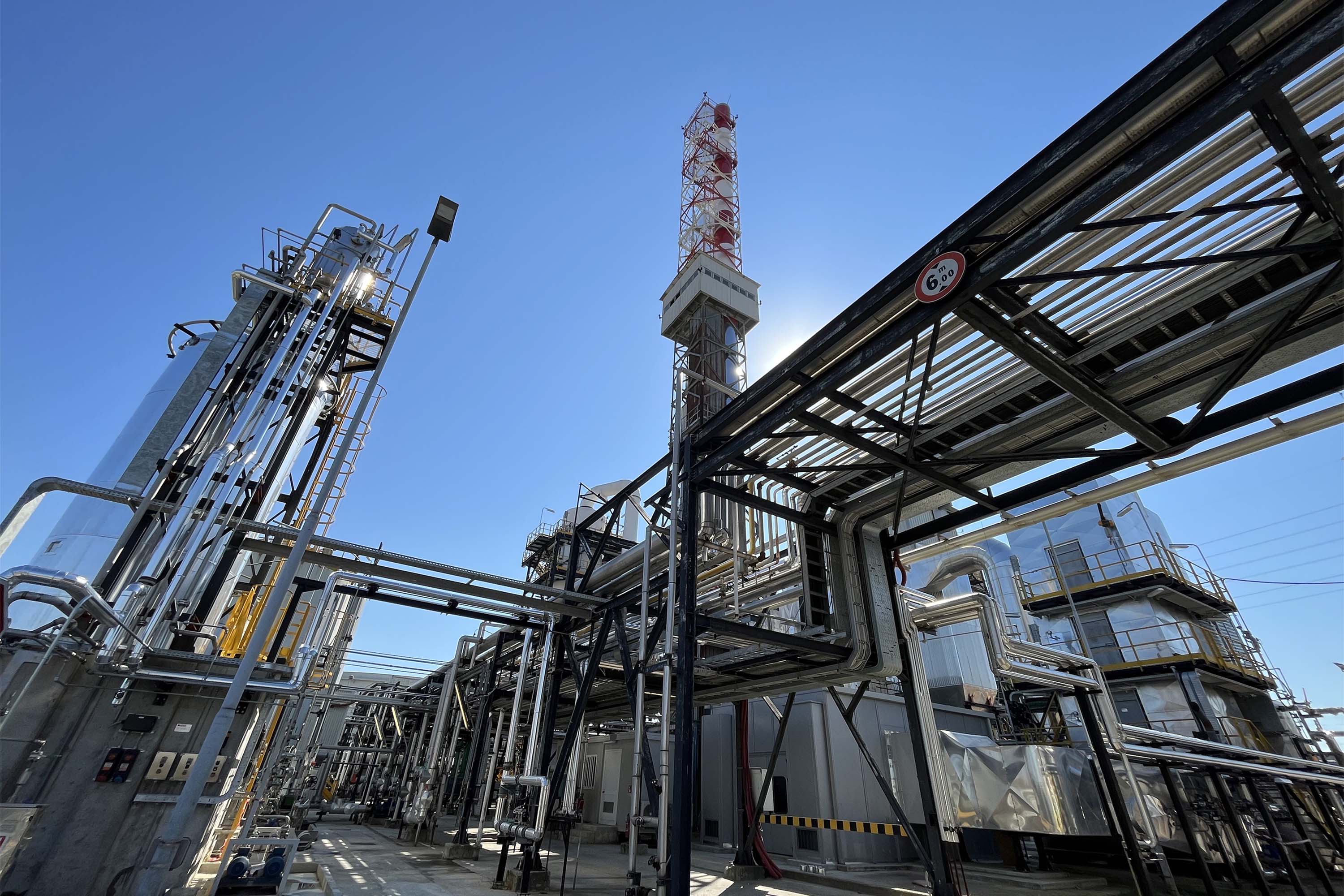
F3 waste-to-energy plant in Ravenna
The incinerator is found inside <br> the Centro Ecologico Baiona, Via Baiona 182, Ravenna
Incinerator
Special waste, including hazardous industrial waste
-
The incinerator is found inside <br> the Centro Ecologico Baiona, Via Baiona 182, Ravenna
Incinerator
Special waste, including hazardous industrial waste
-
The incinerator is found inside <br> the Centro Ecologico Baiona, Via Baiona 182, Ravenna
Incinerator
Special waste, including hazardous industrial waste
Form
-
Number of waste to energy lines
1 -
Total thermal capacity
21.500.000 Kcal/h -
Combustion technology
rotating drum incinerator and static chamber -
Waste disposal capacity
6,5 t/h -
Annual operation
7.700 h -
Nominal electrical power
4,2 MW -
Disposal code
D10 -
Accepted waste
special waste, including hazardous waste of industrial origin (bulk solid waste, solid and liquid waste in drums and boxes, pumpable sludge, organic and inorganic liquid waste)
The waste accepted at the plant is specified in Herambiente's approval procedure. All incoming waste is analytically tested for chemical characteristics.
Reception and storage of solid waste: bulk solid waste delivered by lorry or container is unloaded and stored in a special pit, which can be accessed through fast packing doors. The pit is divided into several similar sections: waste reception and storage section (1,000 m3), uniform loading section for solid waste to be fed into the incinerator (200 m3). The waste is taken from the pit by means of a special overhead crane/bucket system and fed to the incinerator loading hopper, from which it is sent through the conveyor belt to the feed chute. Before being loaded into the feed hopper, it is ground by means of a grinder installed in the upper part of the pit building; the grinder is fed by the overhead crane/bucket system and the ground material is unloaded into the pit through a chute. In order to prevent the spread of dust and diffusion of unpleasant odours into the air, the storage pit is kept normally closed and under vacuum (the air sucked in is used as combustion air)
Incinerator-fed drums containing solid and pasty waste are delivered packed on pallets and stored in a special roofed, paved area with a safety kerb and gutter to collect any spillage. The bundles of solid hospital waste delivered are stored inside a dedicated building waiting to be sent for thermal destruction.
Reception and storage of sludge: delivered by lorry or tanker depending on its characteristics, the sludge is stored in a special hopper with a volume of 60 m3. It is discharged into the hopper either through a hydraulically operated door or through a pipe fitted with an automatic ball shut-off valve. In order to avoid atmospheric emissions during unloading, the hopper is kept under vacuum by means of a centrifugal fan, which feeds the vents back to the static chamber of the incinerator. With the help of a screw pump with bridge breaker, the sludge is transferred to a reciprocating pump at the front of the rotary drum.
Reception and storage of liquid waste: the tanks of the F3 incinerator have a total volume of 1,260 m3. All storage tanks are of the vertical cylindrical type, made of different materials (carbon steel, internally vitrified carbon steel) depending on the chemical and physical characteristics of the waste contained, in order to withstand chemical corrosion. With the exception of the S-621 tank, all tanks are insulated and equipped with a steam coil for heating. All tanks provided with a curved roof are placed in containment basins with wells for the collection of drains. To ensure a constant thermal load, organic liquid waste is taken from the storage tanks and sent to a pair of tanks to prepare a homogenous charge suitable for feeding the incinerator. The liquids are injected inside the incinerator, at the front of the drum and in the static chamber, by atomising lances that enable rapid combustion of the organic component. They are supplied directly from the tanks through closed-loop pipe system in order to ensure recirculation.
The plant is equipped with a rotating drum incinerator made from a thick metal jacket, reinforced in the support areas and lined inside with refractory material. Due to the rotational movement and the slight slope towards the outlet end, the waste advances along the drum until it reaches the outlet where the incinerated slag falls onto the finishing grate to increase mineralisation. Once the slope of the drum has been set, the time the waste remains in the drum is determined by the drum's rotation speed. The finishing grate receives solid waste unloaded from the drum and through the combustion air, which also serves to cool the arch bars, contributes to the oxidation of the carbon contained in the slag and to its mineralisation.
Also at the front are two lances for feeding inorganic waste (wastewater), two lances for feeding direct line waste from tankers and bulk, one lance for feeding pumpable sludge, and a multi-purpose burner operating with methane and/or medium to high net calorific value (NCV) organic waste.
The combustion chamber (or static chamber) is located at the outlet of the rotating drum. This chamber is equipped with 4 multi-purpose burners running on methane and/or 4 lances for inorganic waste, equally distributed over two separate levels.
In the upper part of the static chamber, a multi-purpose burner is used as an auxiliary burner whose operation is automatically controlled by the combustion chamber's outflowing fume temperature controller. The burner is used to supply the fumes with the heat necessary to reach the minimum temperature at the outlet of the combustion chamber.
The plant is in operation at temperatures above 1100°C if it is fed waste with halogens in concentrations above 1%.
Before moving on to the purification section, the fumes leaving the post-combustion chamber is cooled to 220-260 °C in a recovery boiler, resulting in the production of superheated steam at 350 °C and 30 bar. The superheated steam produced in the boiler feeds a turbo-alternator unit with a capacity of 4.2 MW for electricity production.
The electricity produced allows the plant's requirements to be met; the surplus is partly transferred to the neighbouring wastewater treatment plant and to the national supply network.
The electricity produced allows the plant's requirements to be met; the surplus is partly transferred to the neighbouring wastewater treatment plant and to the national supply network.
The fume purification phase includes several pollution abatement systems detailed below. The treatment sequence in the process consists of a non-catalytic DeNOx system (SNCR - Selective Non-Catalytic Reduction) placed in the boiler, then a dust suppression with an electrostatic precipitator placed downstream of the recovery boiler, followed by the fume washing column then a bag filter and catalytic DeNOx system (SCR - Selective Catalytic Reduction) before release into the atmosphere.
The fumes are ready to be released into the atmosphere downstream of the Fume Purification System at a temperature of 110°C, via a special chimney with a height of 60 m and an internal diameter of 1,450 mm.
The F3 incinerator is equipped with a chemical-physical system for the treatment of discharge coming from the fume washing column. The inlet stream is brought to pH 8.5 with milk of lime, added ferric chloride, metal precipitant and anionic polyelectrolyte for flocculation. The water is separated from the sludge with lamellar settling tanks and then filtered over sand beds and activated carbon. The sludge extracted from the settling tanks is sent to a thickener from which it is then extracted to be sent for dehydration in a centrifuge.