-
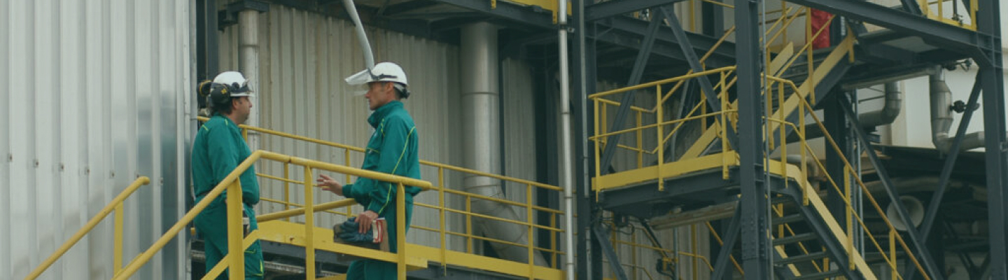
Chemical-physical plant in Pozzilli (IS)
HASI – Viale delle Industrie, snc
Chemical-physical treatment
Wastewater, hazardous and non-hazardous liquid waste
-
HASI – Viale delle Industrie, snc
Chemical-physical treatment
Wastewater, hazardous and non-hazardous liquid waste
-
HASI – Viale delle Industrie, snc
Chemical-physical treatment
Wastewater, hazardous and non-hazardous liquid waste
-
HASI – Viale delle Industrie, snc
Chemical-physical treatment
Wastewater, hazardous and non-hazardous liquid waste
Overview
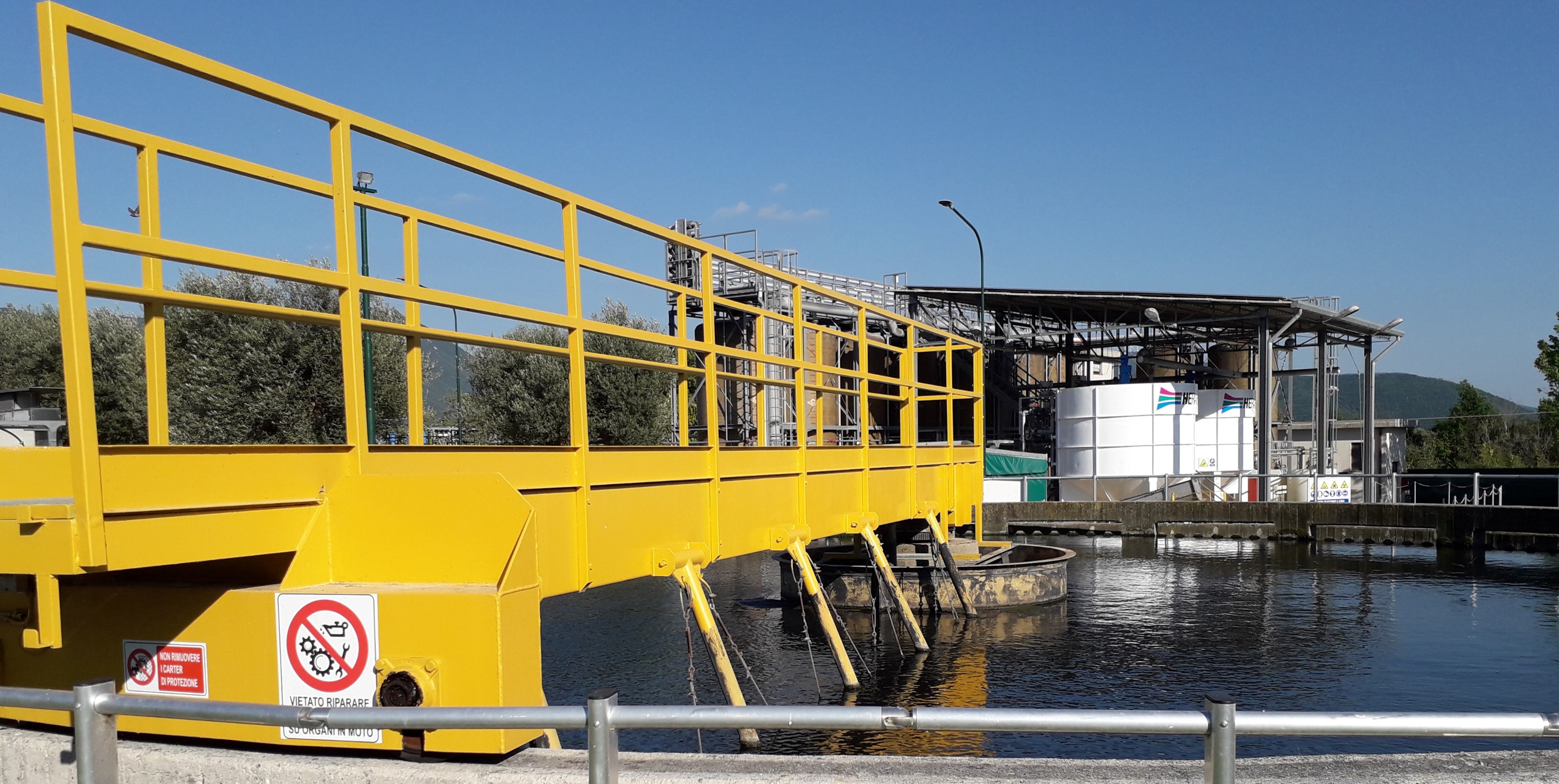
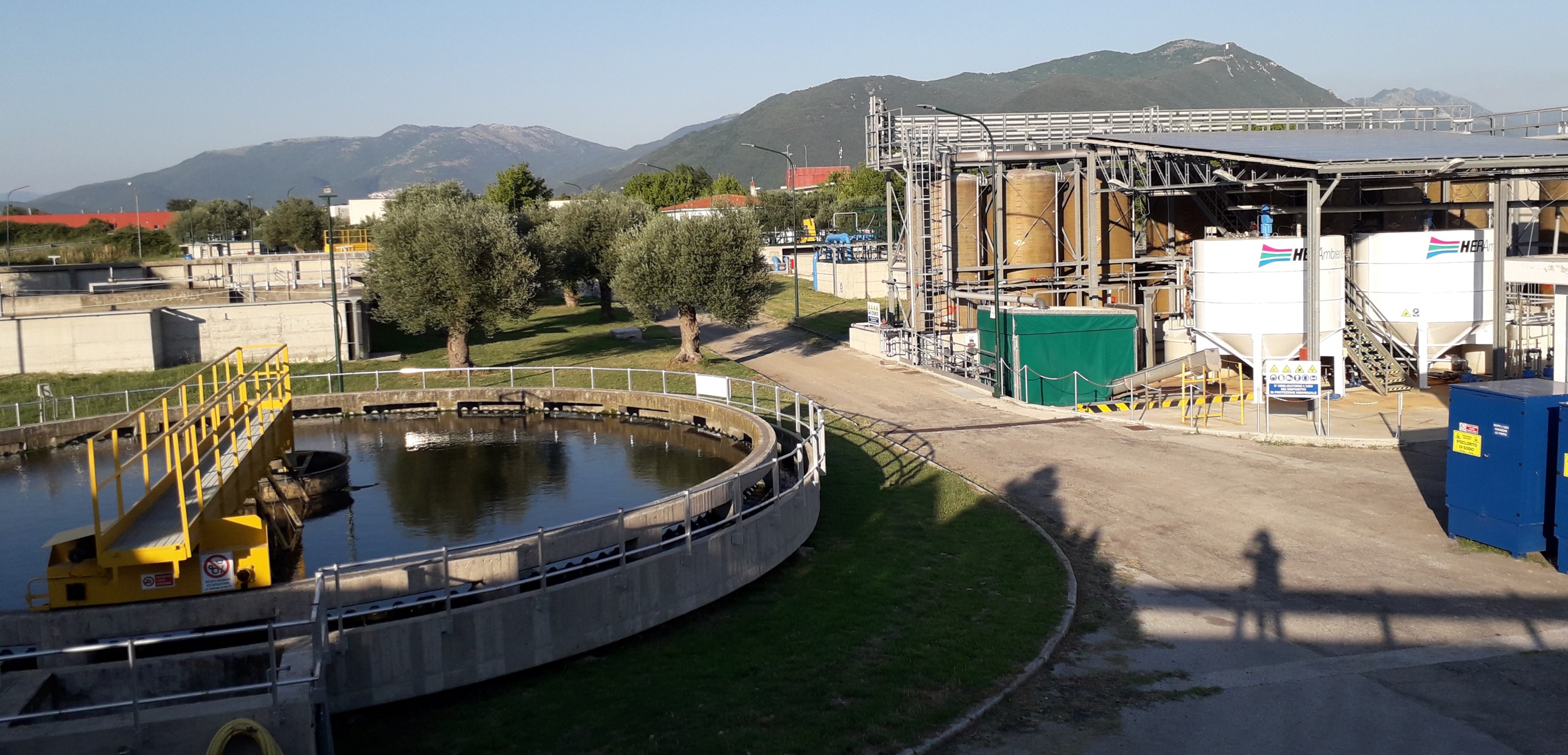
The chemical physical treatment plant, located on an area in the industrial zone of the municipality of Pozzilli (IS), is authorized to treat hazardous and non hazardous liquid waste, wastewater produced by companies located in the industrial core area and some companies outside the area, wastewater from the municipalities of Pozzilli (including some districts) and the municipality of Montaquila (IS), with a total capacity of 27,630 population equivalents.
Page updated 5 December 2022
The process line begins with a manual coarse screening, placed inside the first lift, which is intended to protect the lift pumps, from large bodies. Through the lift pumps are sent to the next stage of initial equalization and homogenization. After the first lift, they contain coarse material and are therefore piped to an automatically cleaned vertical screen. The slurry thus stripped of coarse solids is sent to a tangential inlet (runway) desander. The desanded sewage is subsequently sent to equalization and homogenization tanks. The contents of the tanks are homogenized by means of a floating turbine in the first equalization and, by means of depth insufflators, in the second equalization. The pre-oxidations that are accomplished in the two tanks are intended to prevent anaerobic fermentation processes and thus the appearance of foul odor. The coagulation and flocculation tanks are necessary to specifically remove any dissolved metals and some of the suspended solids. Coagulation is done by introducing ferric chloride or ferrous sulfate into solution. Hazardous liquid wastes with recovery operation can be used as flocculating agents in this section. The slurry added polyelectrolyte and metals in the form of insoluble hydroxides is sent to primary sedimentation and subsequently to oxidative treatment. The final or secondary sedimenter is of the circular plan type with a peripherally driven cleaning overhead crane and central sludge collection hopper. The slurry, water and activated sludge, from the oxidation tanks is decanted and the sludge settles to the bottom of the sedimenter. The clarified water skims overhead by overflow and reaches the contact tank for chlorination. While the sludge is pumped in recirculation to the denitrification stage. Part of the overflow sludge is sent to the sludge treatment line.
The contact tank for disinfection is rectangular in shape with obstacle path to allow higher contact time between the oxidizing agent and wastewater. After the contact tank, the purified water reaches the discharge to surface water. Other disinfectant agents can be used alternatively.
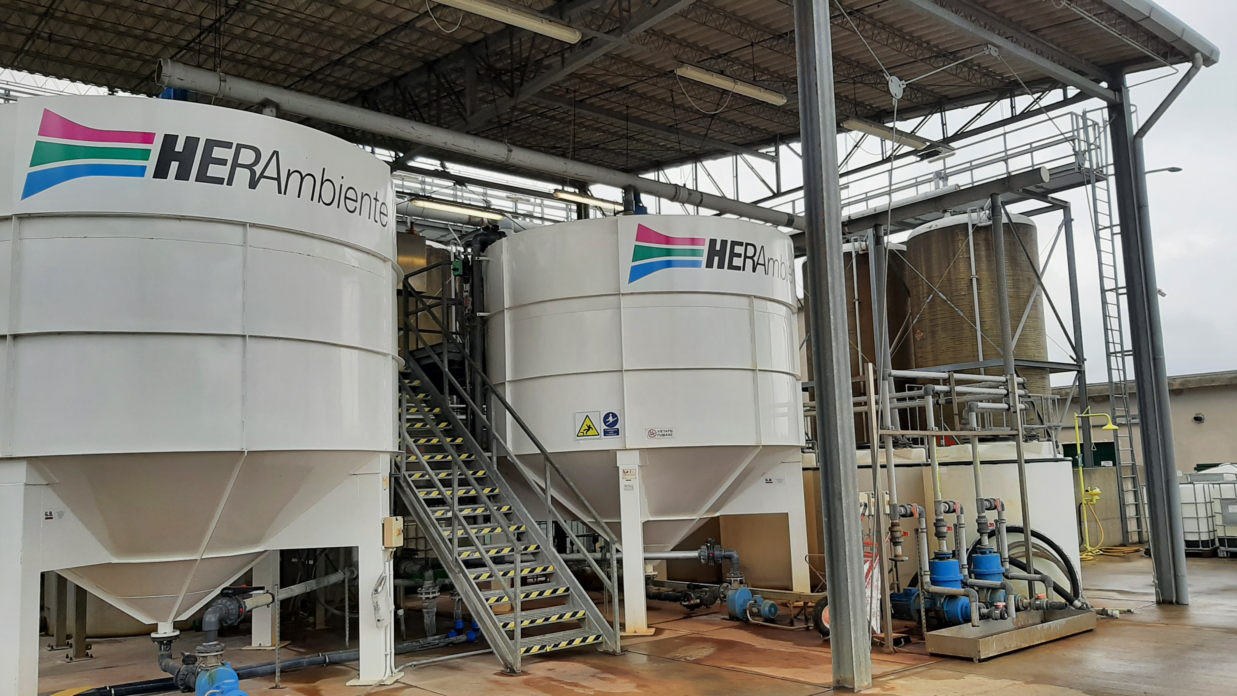
Two truncated conical reactors are installed in the treatment section in which treatment activities take place. From here, appropriate reagents are dosed to allow neutralization, coagulation, flocculation and, if necessary, cold oxidation-reduction operations (e.g., Fenton's reagent). One of the two reactors, if required, can be used as a sludge pre-inspector. From both reactors, after treatment reactions, wastewater is tapped from different heights by opening the appropriate valves. Post-treatment water is sent, after possible analytical control, to the equalization section of the water treatment line. Chemical sludge, extracted from the conical bottom of the two reactors, is sent to the collection well to be subsequently sent to the conditioning and pressing stage.
Chemical conditioning of the mixed sludge is performed with lime hydroxide in aqueous solution and with the addition of polyelectrolyte this in order to increase thickening, slow down anaerobic fermentation phenomena and improve filterability on cloth. Sludge from conditioning, which is still pumpable, is sent to a gravity thickener. The latter is circular in shape and buried.
The mixed sludge thickened and conditioned in the thickener is taken up by a set of three mono pumps and sent to the belt-pressing section. More polyelectrolyte is dosed on the discharge of the pumps to decrease the cohesive forces of the sludge with the water in it. The working cycle of the belt presses consists of two successive stages. In the first stage (predewatering), the sludge falls on top of a first continuous belt; the countertrend of the belt causes a stagnation zone where the heavier particles settle and form a layer capable of retaining the finer particles. In the area below the belt, a certain depression is maintained that promotes the escape of water. In the second stage (dewatering), the panel is pressed between the first web and the second cylinder. The liquid that separates from the sludge and the wash water are sent to the head of the treatment plant as well as the separation water from the gravity thickener. The dewatered sludge, with moisture contents between 60 and 70 percent, exiting the two belt presses through a conveyed belt and a screw conveyor, respectively, is sent to a tank open to the sky and made with four reinforced concrete walls; two openings allow the same sludge to be removed by mechanical shovel. The storage made in this way further reduces the moisture content by both evaporative and drainage effects. Wastewater is sent to the first lift. The storage of produced sludge has a maximum volume of 500 m3. The produced sludge can also be deposited in roll-off skips also within the storage area.
Documents of the facility:
16207Kb - pdf
236Kb - pdf
1116Kb - pdf
1184Kb - pdf
1480Kb - zip
869Kb - zip
20Kb - docx
Safety documents to access the facility:
300Kb - pdf
241Kb - pdf