Overview
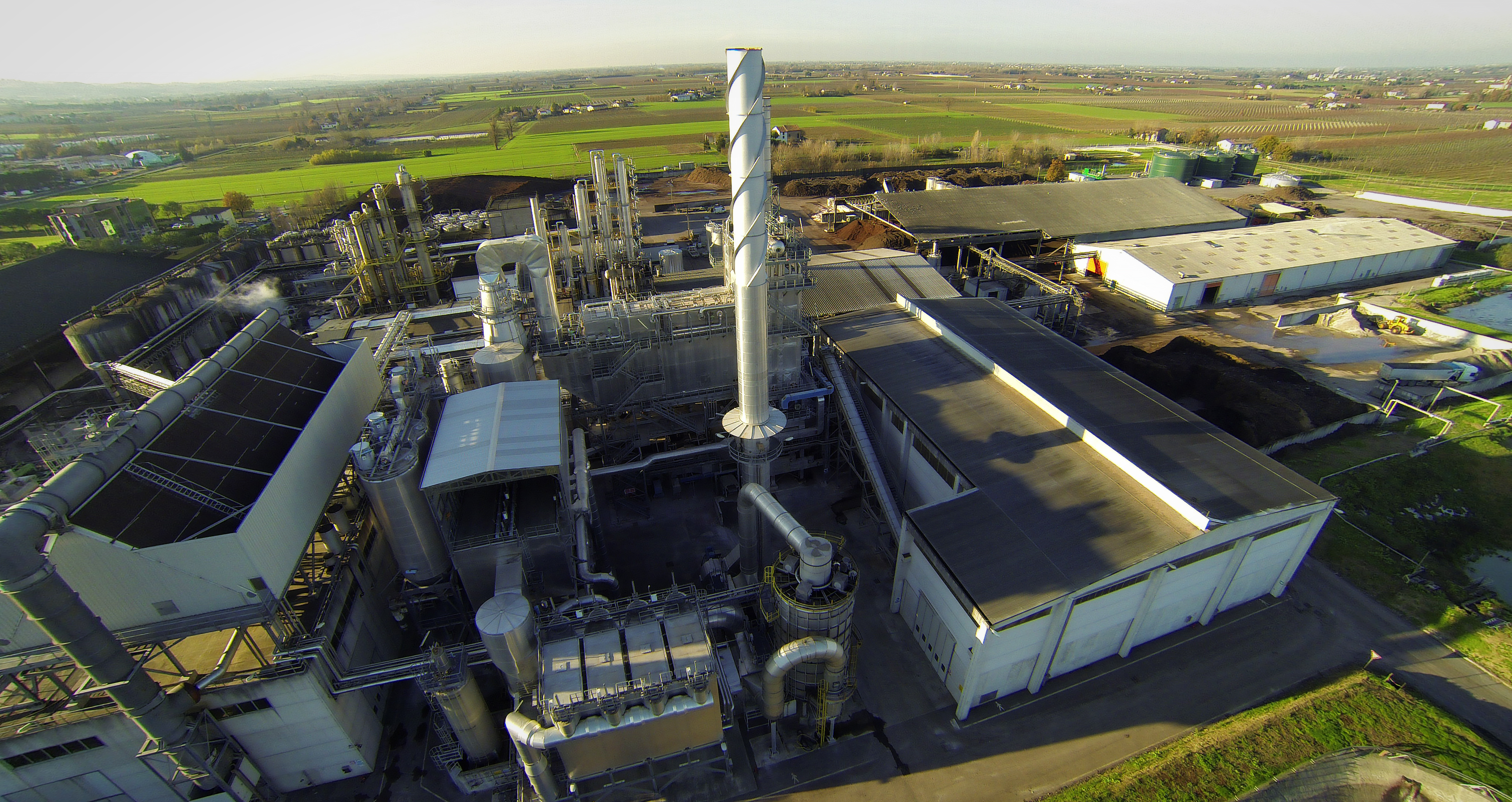
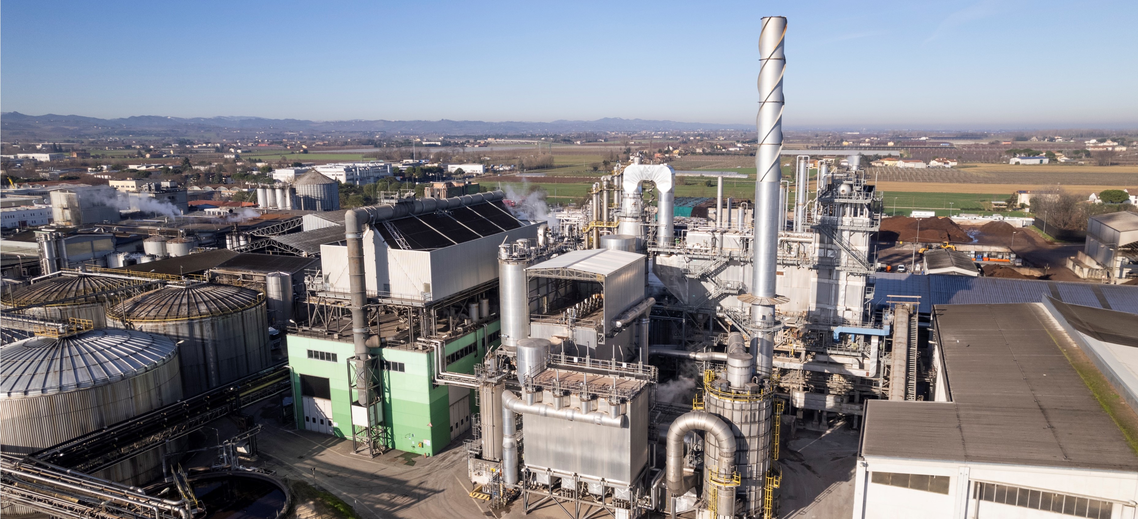
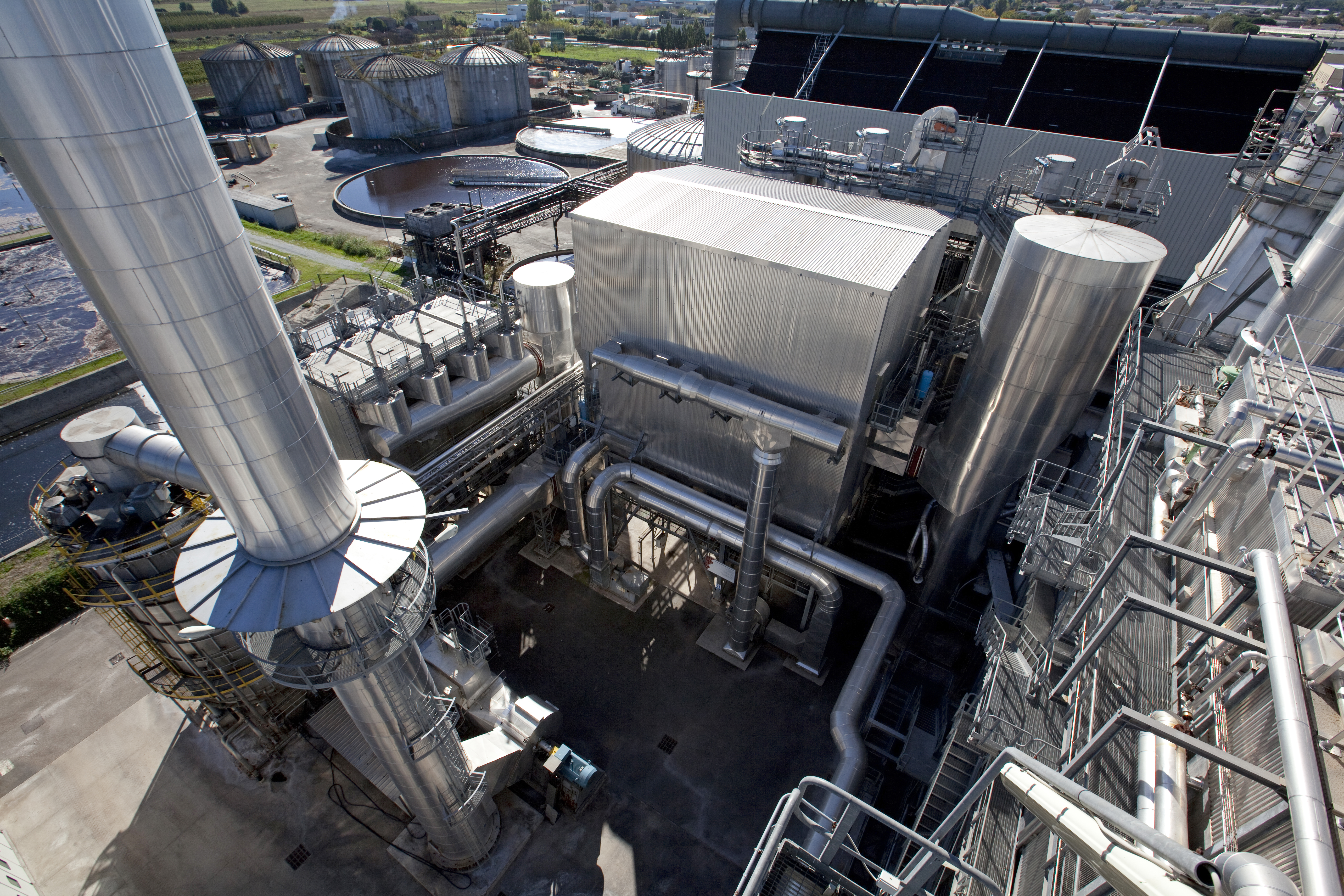
The renewable energy plant consists of a single combustion line, called CTE, which was commissioned in May 2010. The Faenza thermoelectric power plant, powered by renewable energy, draws energy from non recyclable waste, recovering it during waste combustion.
The plant complex also includes three composting plants authorized to process 120,000 tons of organic and lignocellulosic waste for the production of Green Composted Soil Conditioner (ACV), Mixed Composted Soil Conditioner (ACM)—allowed for organic farming—and Composted Soil Conditioner from Agri food Chain Waste (ACFA) for use in conventional agriculture.
-
Number of combustion lines
1 -
Total thermal capacity approximately
approximately 44,5 MWt -
Combustion technology
Air cooled moving grate furnace -
Disposal capacity
approximately 450 t/d with a CVL of 9,378 kJ/kg -
Yearly operation
7,800 h -
Nominal electrical power
13.7 MWe -
Biomass types
Marc; wood; hazardous waste (dry residue); SRF
- Fuel Handling Section: Fuel handling is carried out with mechanical shovels capable of loading and mixing the fuel for the boiler. The mixed fuel is fed into a screw-bed loading hopper; From here, the fuel is transported directly to the boiler's loading hopper via a conveyor belt.
- Combustion chamber fuel feeding system: The loading hopper consists of a sheet metal hopper fed directly from the conveyor belt via a modulating fuel dosing system. The hopper is connected to the furnace via the loading duct that conveys the fuel to the combustion chamber. The ducts are water-cooled. The duct must remain full of fuel during operation to ensure a seal between the inside and outside of the combustion chamber, thus preventing air from entering. A hydraulically operated guillotine gate is located between the base of the hopper and the mouth of the relevant loading duct, which ensures protection of the loading duct from any flame rising from the oven.
To minimize the environmental impact of odors and dust, the vehicles unload directly into the storage shed.
Thanks to the alternating movement of the furnace grate steps, the biomass advances, mixing, until it reaches the combustion chamber. This mixing promotes combustion, reducing the presence of unburned residues in the final slag.
The air required for the combustion process is introduced into the chamber both through the grate (primary air) and through openings in the side walls (secondary air). To increase energy efficiency, before being introduced into the combustion chamber, the primary air is preheated by heat exchangers that use steam produced by the boiler. To ensure complete combustion, the residues then pass to the post-combustion chamber, sized to ensure that the fumes remain at a temperature above 850°C for at least 2 seconds. Maintaining this temperature, even when using biomass with low calorific value, is ensured by two backup burners powered by methane gas, which activate automatically based on the flue gas temperature. The first stage of flue gas purification also takes place in the post-combustion chamber, injecting an ammonia solution to reduce nitrogen oxides (a process called Non-Selective Catalytic Reduction - SNCR). The combustion waste, once it reaches the end of the grate, falls into a water tank to ensure complete extinction and is then transferred to the storage pit via extraction and transport systems.
The water-tube boiler has a dual function: recovering the heat contained in the flue gases and cooling them for subsequent purification stages. The flue gases enter the boiler at approximately 950-1000°C and exit at approximately 180°C, where they are then sent for purification.
- Combustion Chamber Nitrogen Oxide Reduction System (SNCR)
- Quenching Tower
- Chemical Conditioning Tower (Lime/Bicarbonate and Activated Carbon)
- Bag Filter
- Nitrogen Oxide Reduction System (SCR)
- Final Wet Guard Treatment
The turboalternator used in the plant is nothing more than a two-stage condensing turbine, with low-pressure steam bled at the exit of the first stage.
The bled steam (at a pressure of 5 bar A and a temperature of 175 °C) is collected by the low-pressure collector and then sent to the thermal degasser, to the plant's steam users, and to a district heating network serving the Caviro Extra plant, industrial, artisanal, and domestic users in the surrounding area.
The energy produced by the alternator coupled to the turbine shaft is partly used to meet the plant's demands, while the excess amount, approximately 85% of that produced, is sold partly to the Caviro Extra Distilleries plant and partly to the national grid.
The steam discharged from the second stage of the turbine (at a pressure of 0.12 barA and a temperature of 49.4 °C) is sent, via a 1200 mm diameter supply pipe, to a condensing system, which is sized to receive steam in emergency conditions from the turbine's bypass valve group.
The condenser is installed above the roof of the office and service building, while the condensate tank (hot well) and the vacuum unit are installed below it.
Emissions monitoring
The emission point is monitored in accordance with current legislation;
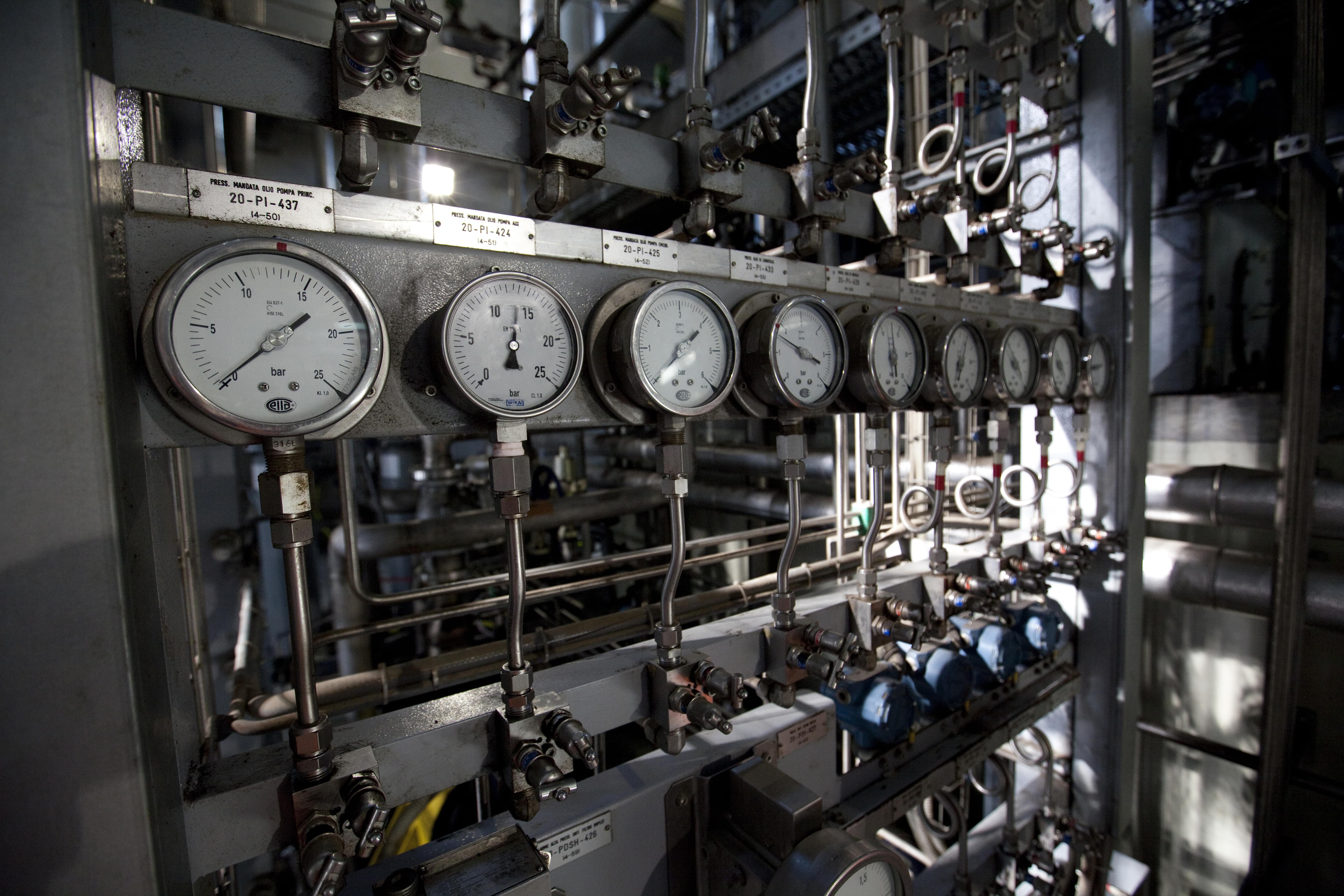
The plant is equipped with a Continuous Emission Monitoring System (CEM) that, through automatic analyzers operating 24 hours a day, allows for constant monitoring of the quality of atmospheric emissions.
A heated sampling probe continuously transports a gas sample from the plant's stack to the analysis booth, where the instrumentation is installed. The sample enters the interferometric infrared spectrometer (FTIR) analyzer, which continuously detects the absorption spectra of the compounds being measured. Through mathematical processing, the present spectra are compared with those typical of the substances being analyzed. This comparison allows for the quantitative values (concentrations) of the elements and compounds being sought to be determined. The FTIR system is complemented by other analyzers and continuous meters necessary to complete the flue gas analysis by determining additional parameters such as dust, organic compounds, oxygen, temperature, flow rate, and pressure.
A data acquisition system makes the continuously acquired values available by processing semi hourly and daily averages of the measured concentrations, which are compared with the maximum permissible limit values set by the control bodies.
Documenti dell'impianto:
1480Kb - zip
869Kb - zip
20Kb - docx


